
RF Coaxial Attenuators
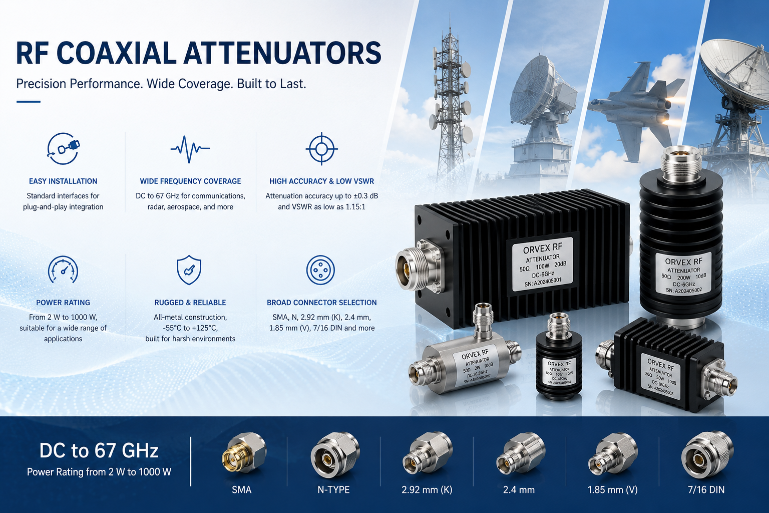
ORVEX RF coaxial attenuators are engineered for modern RF and microwave systems, covering a wide frequency range from DC to 67 GHz and offering power ratings from 0.5 W to 1000 W. Utilizing precision thin-film resistor networks and high-stability substrate technology, these attenuators are available with a full range of standard coaxial interfaces, including SMA, N, 3.5 mm, 2.92 mm, 2.4 mm, 1.85 mm, and 7/16 DIN.
RF Coaxial Attenuators
Key Benefits
Ultra-Broadband, High-Accuracy Attenuation
Available from 1 dB to 60 dB with typical accuracy better than ±0.5 dB up to 18 GHz. Excellent flatness is maintained even in mmWave bands for precise signal amplitude control.
Full-Band Low VSWR for Superior Signal Integrity
Optimized absorptive topology delivers typical VSWR below 1.25:1 across the full band, reaching as low as 1.10:1 at lower frequencies. Reflections are minimized to preserve signal quality in cascaded chains.
High Power Handling with Efficient Thermal Management
Medium/high-power models rated from 50 W to 1000 W CW, featuring integrated heat sinks and air- or water-cooling options. Peak power handling exceeds 10x average power, ideal for radar pulse applications.
Complete Coaxial Interface Range, Wideband Compatibility
Connectors cover DC to 67 GHz (SMA, N, 3.5 mm, 2.92 mm, 2.4 mm, 1.85 mm, 7/16 DIN, and more). Precision interfaces are mechanically compatible, reducing adapter requirements and system cost.
Rugged Reliability in Extreme Environments
Industrial-grade operating range from -55°C to +125°C. Stainless steel bodies and hermetic sealing withstand salt fog, vibration, and thermal shock. Connectors rated for over 5,000 mating cycles with minimal degradation.
Flexible Customization and Fully Traceable Data
We support non-standard dB values, special connector combinations, and integrated bias-tee designs, with rapid delivery for small batches. Every unit includes a full-band S-parameter test report for complete traceability.
50 Ω RF Coaxial Attenuator Specifications by Connector Type
| Connector Type | Typical Frequency Range | Typical Power Capacity (CW) | Maximum VSWR | Attenuation Accuracy (Typical) | Common Attenuation Values | Typical Features & Applications |
|---|---|---|---|---|---|---|
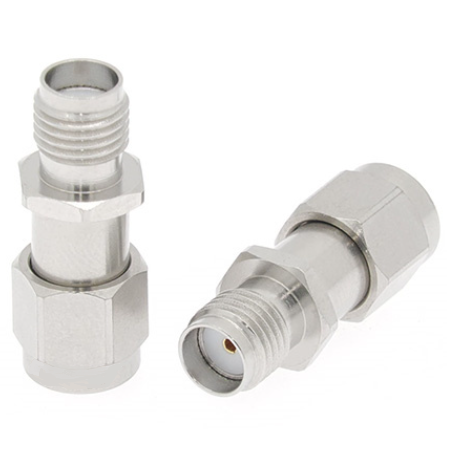
| SMA | DC–26.5 GHz) | ≤10 W | ≤1.15 / 1.25 / 1.35 | ±0.5 dB, ±0.8 dB | 1,3,6,10,15,20,30 dB | General-purpose; instrument port protection and RF module testing |
| N | DC–18 GHz | 2–500 W | ≤1.15 / 1.25 / 1.35 | ±0.5 dB, ±1.0 dB | 3,6,10,20,30 dB | Medium/high-power testing, antenna feeders, base-station IMD testing |
| 3.5 mm | DC–33 GHz | ≤2 W | ≤1.20 / 1.35 / 1.50 | ±0.5 dB, ±1.2 dB | 3,6,10,20 dB | Precision network analyzers; mechanically compatible with SMA |
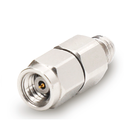
| 2.92 mm (K) | DC–40 GHz | ≤2 W | ≤1.25 / 1.40 / 1.55 | ±0.8 dB, ±1.5 dB | 3,6,10,20 dB | Millimeter-wave communications and radar testing |
| 2.4 mm | DC–50 GHz | ≤1 W | ≤1.30 / 1.50 / 1.70 | ±1.0 dB, ±2.0 dB | 3,6,10,20 dB | 50 GHz millimeter-wave systems and ultra-wideband testing |
| 1.85 mm (V) | DC–67 GHz | ≤0.5 W | ≤1.40 / 1.60 / 1.80 | ±1.5 dB, ±2.5 dB | 3,6,10 dB | 60 GHz millimeter-wave, high-speed digital testing, defense electronics |
| BNC | DC–4 GHz | ≤2 W | ≤1.15 / 1.30 | ±0.3 dB, ±0.5 dB | 3,6,10,20 dB | Video, low-frequency RF, oscilloscope/signal generator ports |
| TNC | DC–18 GHz | ≤50 W | ≤1.15 / 1.25 / 1.35 | Comparable to N/SMA | 3,6,10,20,30 dB | Threaded-lock connector for vibration environments |
Note: Specifications shown are for reference only. Customized solutions are available, from standard product modifications to fully custom designs. Contact us for detailed specifications and technical documentation.